Choosing a Central Driving Concentrator is not just a matter of matching tank diameter to plant capacity. In mineral processing, the right unit must handle the expected feed while supporting reliable settling, clear overflow, and manageable underflow. A mismatch can show up as rising torque, uneven rake movement, or solids collecting where operators do not expect them. Small details matter.
Start with the material. Confirm feed rate, solids concentration, particle-size distribution, and settling behavior using representative process data. Then compare these figures with the concentrator’s rated capacity and operating limits. Ask how the supplier calculates rake torque and what happens if the feed becomes denser than planned. One test result may not reflect every shift. That is worth remembering.
The site matters too. Check available space, foundation requirements, access for maintenance, and the conditions around the tank, including temperature and corrosion exposure. Review the drive arrangement, control features, wear parts, and access to technical support. Request drawings and duty-specific specifications, not only a general product brochure. Where possible, have a process engineer verify the selection against actual operating data. A lower purchase price may look attractive, but maintenance access and energy use affect ownership over time. No single model fits every plant. The best choice is the one supported by evidence, clear operating requirements, and a realistic plan for inspection and service.
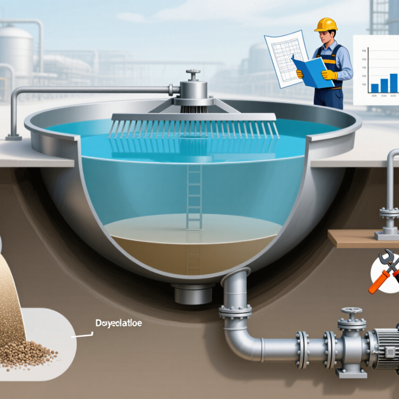
A central-drive concentrator does more than turn a rake. Its drive transfers torque to the rake arms, which guide settled solids toward the central discharge while helping prevent buildup on the tank floor. This matters when feed solids vary during a shift.
EPA’s Biosolids Technology Fact Sheet on Gravity Thickening reports typical thickened sludge concentrations of about 2–6%, depending on feed and operation. That range is a useful reference, not a promise for every process.
When selecting a unit, match drive torque and rake design to tank diameter, solids loading, and the material’s settling behavior. WEF and ASCE design guidance also treats process loading and equipment capacity as connected choices. Ask for calculations based on actual feed data, not just nominal capacity.
Check access to the drive, overload protection, and how operators can inspect the rake. One detail is easy to miss: fibrous or sticky solids may behave differently from ordinary sludge. I would verify this with a representative sample or pilot test. It takes extra time. Yet a neat catalog value can hide an awkward operating problem.
Specify the concentrator from the slurry outward. Measure feed solids, particle-size distribution, mineral density, clay content, pH, temperature, and seasonal variation. A sieve result alone can mislead; ultrafines often control settling and yield stress. Test representative samples, not just freshly prepared laboratory pulp. Real plant feed is messier.
Define the duty in measurable terms: dry-solids throughput, feed rate, underflow density, overflow clarity, and expected fluctuations. Record feed and target underflow solids by mass, then test performance across operating conditions.
The U.S. Geological Survey’s Mineral Commodity Summaries 2024 estimated 2023 world copper mine production at about 22 million metric tons. That figure does not size a unit, but it shows why throughput and feed variability should be measured, not guessed.
Check rake torque, bed depth, drive overload response, and feedwell performance against the tested slurry. Include flocculant or wash water only when the process requires it. Trials should assess settling speed and overflow turbidity together. Ask for normal and upset-case results. Often skipped. Laboratory settling rates may not transfer directly to full-scale equipment, so confirm the design basis with pilot or operating data when available.
A central driving concentrator should be sized from measured slurry behavior, not feed tonnage alone. Capacity depends on solids concentration, particle settling rate, and the required overflow clarity. Run settling tests on representative samples, including difficult ore blends. Small changes in clay content can slow settling sharply. The SME Mineral Processing and Extractive Metallurgy Handbook describes testwork as a basis for thickener design; treat catalog capacity as a starting point, not a guarantee. Check both dry-solids throughput and hydraulic loading.
Drive power and torque need separate attention. A unit may handle normal operation yet struggle when settled solids build up after a shutdown. Review rake torque, startup load, and overload protection against the thickest expected bed. The U.S. Department of Energy’s 2014 report, Improving Motor and Drive System Performance, estimates that motor-driven systems use about 68% of U.S. manufacturing electricity. That broad figure is not a concentrator benchmark, but it shows why efficient motor selection and control matter. Don’t oversize by guesswork.
Structural design matters just as much. Inspect the bridge span, central column, rake arms, and tank interface for load paths, corrosion allowance, and maintenance access. A tight walkway can make routine inspection awkward. Ask for design loads under both steady operation and upset conditions, then compare the assumed slurry density with site measurements. These details are easy to overlook. We still need better operating data for unusual ore blends, so leave room for adjustment.
Compare capacity, drive power, and structural design
The chart compares representative 10 m, 20 m, and 30 m thickener diameters. Estimated hydraulic throughput is calculated from settling area × an assumed surface loading of 0.5 m³/m²/h. Drive-power figures are indicative examples, not equipment ratings; actual requirements depend on slurry properties, bed depth, rake torque, and duty.
Larger units provide more settling area but require careful structural design. Compare bridge or column support, center-drive loading, rake strength, and foundation requirements alongside process capacity and drive power.
A central driving concentrator should be selected for the actual slurry, not by tank diameter alone. Check feed rate, solids concentration, particle size, and settling behavior using representative samples. Confirm that the site can support the tank, bridge, drive, and stored solids. A level-looking slab does not prove adequate capacity; ask a qualified engineer to review the foundation and ground conditions.
Access deserves equal attention. Leave room for lifting equipment, inspection, and rake removal, and check overhead restrictions before delivery. Review feed and overflow routing, drainage, wind exposure, and freezing risk. During installation, verify tank level, bridge alignment, drive mounting, rake clearance, and anchor placement against approved drawings. Take measurements before grouting. Small corrections become difficult later.
Set a maintenance plan before commissioning. Record baseline motor current, gearbox temperature, vibration, and rake torque under normal feed conditions. Inspect lubricant, seals, fasteners, scraper blades, and corrosion on a defined schedule; track changes rather than waiting for visible failure. Keep access platforms clear and isolation points reachable. Conditions change, and an operating assumption can be wrong. Review trends with site operators and adjust inspection intervals to actual wear and process variability.
How to Choose a Central Driving Concentrator?
Verify Safety Standards and Supplier Support
Before choosing a central driving concentrator, confirm which safety standards apply to its intended use and installation location. Ask for current test reports, product declarations, and clear instructions for setup and routine checks. Verify document details with the issuing organization when possible. A certificate alone can look reassuring, but it may not cover every configuration. I would not rely on a polished brochure as proof; that is an easy mistake.
Supplier support matters after delivery. Ask who handles installation questions, how quickly service requests are answered, and whether replacement parts will remain available. Request a sample maintenance schedule and written warranty terms. A useful supplier should explain alarms and operating limits in plain language, not just send a technical sheet. Keep the answers on file. Small details matter.
Tips: Check labels on the unit against its documents. Ask for hands-on training, a named service contact, and guidance for routine fault checks. If answers stay vague, pause and compare options. The checklist may feel tedious, and it can miss things, so have a qualified professional review the setup before use.
| Evaluation Dimension | What to Verify | Evidence of a Suitable System | Warning Signs |
|---|---|---|---|
| Applicable safety standards | Confirm which medical-device, medical-gas, and facility requirements apply in the installation’s jurisdiction and intended use. | Current certificates and test documentation identify the exact system or components covered, the applicable standards, and any limitations. For pipeline supply systems, check whether ISO 10083 applies; also review applicable electrical-safety and local healthcare-facility requirements. | Unverifiable certificates, expired documents, or claims that a single standard automatically covers every part of the installation. |
| Oxygen concentration and quality | Check the specified oxygen concentration range, monitoring method, alarm settings, and acceptance criteria against the applicable medicinal-gas specification and local rules. | Technical documents state the required product specification and describe continuous or defined-interval monitoring. If an Oxygen 93 specification is applicable, confirm its limits and testing method against the governing pharmacopoeia and local requirements. | A purity figure is quoted without test conditions, monitoring details, or a reference to the applicable specification. |
| Capacity and outlet performance | Assess delivered flow and pressure at the required operating conditions, including peak demand and the planned number of connected outlets. | Documented sizing calculations and commissioning tests show that the system meets the facility’s design demand while maintaining the specified pressure and oxygen quality. | Capacity is stated only as a maximum under unspecified conditions, or no demand calculation is provided. |
| Alarms and fault detection | Review alarms for low oxygen concentration, pressure deviations, power failure, equipment fault, and other risks relevant to the design. | Alarm functions, set points, locations, and response procedures are documented and verified during commissioning. Staff can identify and respond to each alarm. | Alarms are not included in the scope, cannot be tested, or have no clear escalation procedure. |
| Continuity and backup supply | Determine how supply is maintained during maintenance, power interruption, equipment failure, or demand beyond normal operating conditions. | The design includes a documented backup or changeover arrangement appropriate to the facility’s risk assessment, along with tested operating and emergency procedures. | No defined backup source, changeover method, or plan for an extended outage. |
| Installation and commissioning | Clarify responsibilities for site preparation, pipeline connection, testing, staff training, and handover documentation. | A commissioning plan includes functional and safety checks, recorded test results, operating instructions, maintenance schedules, and training records. | Installation acceptance relies only on a verbal assurance or omits test records and operator training. |
| Maintenance and spare parts | Verify preventive-maintenance intervals, service access, parts availability, warranty terms, and the expected service life of key components. | The supplier provides a written maintenance schedule, clear warranty coverage, parts-support arrangements, and documented service procedures. | Maintenance requirements or parts lead times are unclear, or routine service depends on undocumented procedures. |
| Supplier support and response | Ask about technical support hours, emergency escalation, service coverage, remote diagnostics, and response commitments. | Support terms are documented, including contact routes, escalation steps, service scope, and response targets suitable for the facility’s operational risk. | Support promises are informal, emergency contacts are unavailable, or responsibilities between supplier and installer are not defined. |
Selection note: Confirm requirements with the facility’s clinical engineering, medical-gas, and regulatory teams. Applicable standards and acceptance limits depend on the system design, intended use, and jurisdiction.
